

Blog & Technical Insights
Stay updated with the latest technological developments, industry insights, and news on Lithium Iron Phosphate (LFP) batteries and custom energy solutions.
What Are Battery Management Systems and How Do They Work?
Table of Contents
A battery pack may look like a simple row of cells, but its performance depends on constant measurement and control. Battery Management Systems monitor voltage, current, temperature, and state of charge. They also estimate state of health, balance individual cells, and disconnect the pack when conditions become unsafe. In an electric vehicle, this work happens while the battery faces vibration, rapid charging, cold mornings, and repeated acceleration.
Battery engineer Davide Andrea, author of Battery Management Systems for Large Lithium-Ion Battery Packs, describes the BMS as “the brain of the battery pack.” The comparison is useful, although not perfect. A BMS does not understand every chemical change inside a cell. It interprets sensor data and applies models, limits, and protection rules. Small errors can matter. A temperature sensor placed several centimeters from a hot cell may report a safer reading than reality.
This guide explains what Battery Management Systems are and how they work in practical terms. It follows the path from cell monitoring to pack-level decisions, including passive balancing, active balancing, thermal control, communication, and fault detection. It also considers a common weakness: battery estimates are not direct measurements. They are informed calculations. Good design combines accurate sensors, validated software, careful testing, and conservative safety limits. One detail is easy to overlook. A BMS protects the battery, but it cannot repair damaged cells or replace sound engineering. Understanding that boundary makes the technology clearer, more reliable, and easier to evaluate.
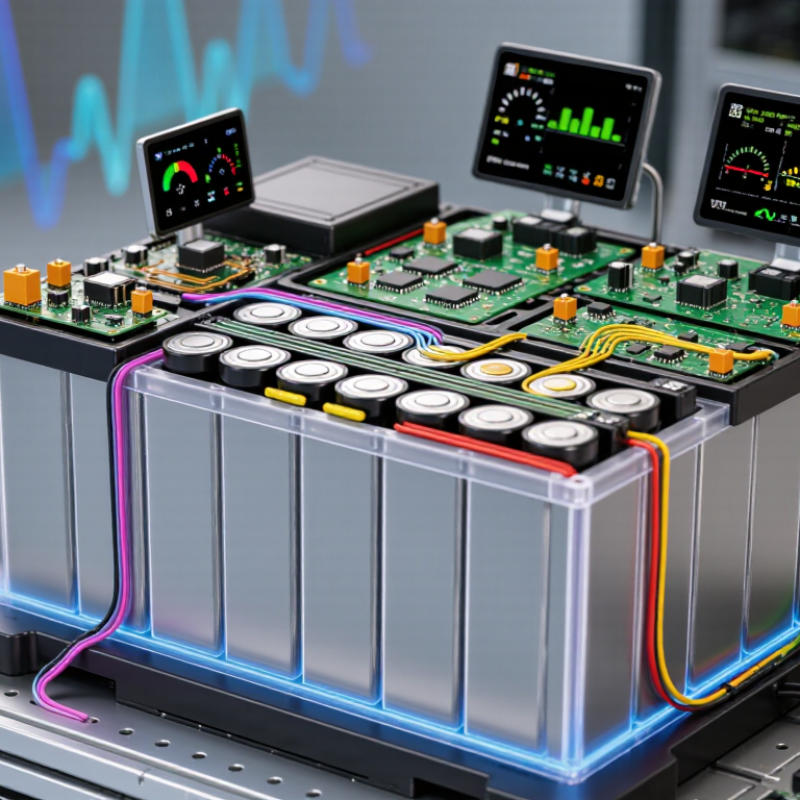
What Is a Battery Management System?
A battery management system (BMS) is the electronic control layer that supervises a rechargeable battery pack. It measures cell voltage, current, temperature, and sometimes insulation resistance. These readings reveal whether the pack is operating within safe limits. A BMS also estimates state of charge and state of health. Those estimates are useful, but never perfectly exact. Cell chemistry, age, and temperature can distort them.
Inside the pack, the BMS balances cells so one cell does not reach a harmful voltage before the others. Passive balancing usually removes small excess energy as heat. Active balancing can move energy between cells. The system may disconnect charging or load current when it detects overvoltage, overheating, excessive current, or a short circuit. In practical testing, sensor placement matters greatly. A sensor far from a warm connection may report a reassuring but incomplete picture. Communication circuits can also send operating data to chargers, vehicles, or monitoring equipment.
Tips: Keep temperature sensors firmly attached to the intended surfaces. Check voltage readings against calibrated instruments during maintenance. Do not rely on percentage displays alone; sudden changes can indicate imbalance or aging. Record unusual heating, reduced runtime, and repeated protection events. These details help technicians distinguish a weak cell from a faulty sensor, although diagnosis sometimes requires controlled testing and careful judgment.
The Core Components of a Battery Management System
A battery management system (BMS) is the control layer that keeps a rechargeable battery safe, balanced, and useful. Its core components work together inside a compact enclosure, often near the battery cells. Voltage and temperature sensors measure each cell repeatedly. Current sensors track charge and discharge flow. These readings help the BMS estimate state of charge (SOC) and state of health (SOH). The estimates are useful, but never perfect.
The BMS controller processes sensor data against programmed safety limits. If a cell becomes too hot, too cold, or overcharged, it can reduce current or stop operation. Contactors and fuses provide physical protection during serious faults. Cell-balancing circuits correct voltage differences between cells. Passive balancing releases extra energy as heat, while active balancing transfers energy between cells. Thermal controls may operate fans, pumps, or heating elements. Communication circuits also report warnings and measurements to external equipment.
Tips: Place temperature sensors close to likely heat sources, not only at the pack edge. Check sensor calibration during maintenance. A small wiring fault can distort every safety decision. Keep clear records of voltage, temperature, and fault history. In practice, balancing thresholds require careful testing because a setting that works for one battery design may perform poorly in another. Never treat the displayed SOC as an exact measurement.
How a Battery Management System Monitors Battery Conditions
A battery management system, or BMS, monitors the conditions inside a battery pack. It measures each cell’s voltage, pack current, and temperature through connected sensors. These readings help estimate state of charge and state of health. A BMS does not simply count energy. It compares live measurements with safe operating limits.
During charging, the system checks whether one cell rises faster than the others. If a cell reaches a high voltage early, the BMS can reduce charging or open the protection circuit. Balancing circuits may release small amounts of energy from stronger cells. This keeps cell voltages closer together. During use, the BMS watches current spikes, heat near terminals, and unusual voltage drops. A sudden change can indicate a loose connection, aging cell, or internal resistance problem.
A displayed percentage can still be wrong. Sensors drift, wiring develops resistance, and temperature affects voltage readings. In cold conditions, a battery may show a reasonable charge level but deliver less power. Reliable systems therefore record measurements over time, not just single values. Technicians can compare these records with charging history and thermal events. Calibration also matters. An incorrect sensor may cause unnecessary shutdowns or miss a developing fault. The BMS must respond carefully, because a limit that works in a warm workshop may not suit a battery operating outdoors.
How Battery Management Systems Protect and Balance Cells
What Are Battery Management Systems and How Do They Work?
A battery management system, or BMS, acts like a careful supervisor inside a battery pack. It measures cell voltage, current, temperature, and charging status continuously. Its main duty is protection. If one cell overheats or falls below a safe voltage, the BMS can reduce current or disconnect the pack.
Cell balancing is equally important. Small voltage differences grow during repeated charging. Passive balancing releases extra energy as heat through resistors. Active balancing transfers energy from stronger cells to weaker ones. This process helps prevent capacity loss and uneven aging. The International Energy Agency’s Global EV Outlook 2024 reported nearly 14 million electric car sales in 2023. It also recorded electric vehicle battery demand above 750 GWh. At this scale, even minor balancing errors can affect safety and usable range. BloombergNEF’s 2024 Battery Price Survey reported average pack prices of 115 dollars per kWh. Protecting that stored value is not optional.
Tips: Keep temperature sensors close to the hottest cells. Review voltage differences under load, not only at rest. Set conservative limits when data quality is uncertain. A BMS is not flawless. Sensors drift, models simplify real behavior, and balancing may be slower than expected. That deserves regular testing.
What Are Battery Management Systems and How Do They Work?
Typical voltage reference points used by a BMS to protect and balance a 4.2 V lithium-ion cell
A Battery Management System monitors each cell and disconnects charging or discharging when voltage approaches unsafe limits. During charging, passive balancing commonly begins near the upper-voltage region by bleeding a small amount of energy from higher-voltage cells, helping the cells reach a more even state of charge. Exact limits vary by cell chemistry and pack design.
Where Battery Management Systems Are Used and Why They Matter
What Are Battery Management Systems and How Do They Work?
Battery management systems are used wherever rechargeable cells must operate safely, reliably, and efficiently. Electric vehicles use them to monitor cell voltage, temperature, current, and charging status. Stationary energy-storage systems depend on them during peak demand, grid outages, and renewable-energy fluctuations. They also support electric buses, medical equipment, telecommunications backup, industrial tools, and small mobility devices.
The International Energy Agency reported nearly 14 million electric cars were sold worldwide in 2023. That scale increases the need for accurate battery monitoring. The IEA also reported that global battery-storage additions rose sharply in 2023, supporting solar and wind integration. A management system balances cells, limits unsafe charging, estimates remaining energy, and records performance changes. In practice, it may detect one overheated module before a cabinet becomes dangerously hot. The process is technical, but the goal is simple: protect people, equipment, and battery life.
Tips: Check sensor calibration during maintenance. Keep cooling paths clear. Review fault logs instead of deleting them. Use measured data to adjust charging limits. No system is flawless. A sensor can drift, and software can misjudge aging cells. Engineers should test unusual conditions, not only normal operation. Reports from the IEA and the National Renewable Energy Laboratory show that battery durability depends on temperature, charging patterns, and operating conditions. That evidence matters when selecting protection thresholds.
| BMS Dimension | What the System Monitors | How the BMS Works | Typical Data or Operating Range | Why It Matters | Common Applications |
|---|---|---|---|---|---|
| Cell Voltage Monitoring | Voltage of each individual cell or parallel cell group | The BMS continuously measures cell voltages and identifies cells that are overcharged, excessively discharged, or significantly different from the rest of the pack. | Lithium-ion cells commonly operate at approximately 2.5–4.2 V per cell, depending on chemistry and design. | Prevents cell damage, capacity loss, thermal stress, and unsafe operating conditions. | Portable electronics, electric vehicles, energy-storage systems, power tools, and medical equipment |
| Pack Voltage Monitoring | Total voltage across the battery pack | The BMS compares measured pack voltage with expected limits and communicates the value to the charger, inverter, or host controller. | Pack voltage depends on the number of series-connected cells; common systems range from under 12 V to several hundred volts. | Supports accurate power control and helps detect wiring, connection, or measurement faults. | Consumer devices, low-voltage mobility, electric vehicles, and stationary storage |
| Temperature Monitoring | Cell, module, busbar, and electronics temperature | Temperature sensors provide feedback for charging, discharging, cooling, heating, and emergency shutdown decisions. | Many lithium-ion systems restrict charging near or below 0°C and reduce operation at elevated temperatures; exact limits are chemistry-specific. | Reduces the risk of accelerated aging, lithium plating, thermal runaway, and performance loss. | Electric vehicles, battery storage, drones, laptops, and industrial equipment |
| Current Measurement | Charge current, discharge current, and current direction | A current sensor measures energy entering or leaving the pack. The BMS uses this information for protection and state estimation. | Permitted current is defined by cell chemistry, pack design, temperature, state of charge, and manufacturer specifications. | Prevents overcurrent, short-circuit damage, excessive heating, and inaccurate battery calculations. | All rechargeable battery packs, including mobility, electronics, and grid-storage systems |
| Overcharge Protection | Cell voltage during charging and charging current | When a cell approaches its upper safety limit, the BMS can reduce or disconnect charging through switches, relays, or charger communication. | For many conventional lithium-ion cells, the upper charge limit is around 4.2 V per cell, but it varies by chemistry. | Protects against capacity degradation, internal damage, gas generation, and possible thermal events. | Rechargeable consumer products, electric vehicles, and stationary battery systems |
| Over-Discharge Protection | Cell voltage while the battery is supplying power | The BMS disconnects the load or requests power reduction when one or more cells reach the configured lower limit. | Many lithium-ion systems use a lower operating limit near 2.5–3.0 V per cell, depending on design. | Prevents irreversible cell damage, copper dissolution, and reduced usable capacity. | Portable electronics, power tools, electric mobility, and backup power |
| Cell Balancing | Voltage and estimated state of charge differences between cells | Passive balancing releases small amounts of excess energy as heat. Active balancing transfers energy between cells or cell groups. | Balancing may begin when cell voltage or estimated state-of-charge differences exceed a configured threshold. | Improves usable pack capacity and prevents the highest or lowest cell from limiting the entire pack. | Multi-cell lithium-ion packs, electric vehicles, and large energy-storage systems |
| State of Charge (SoC) | Estimated remaining charge, expressed as a percentage | The BMS combines current integration, voltage behavior, temperature, and battery-history data to estimate remaining charge. | Displayed on a 0–100% scale; the value is an estimate rather than a direct physical measurement. | Helps users and control systems manage runtime, charging decisions, and available power. | Electric vehicles, mobile devices, renewable-energy storage, and backup systems |
| State of Health (SoH) | Available capacity, resistance, power capability, and aging indicators | The BMS compares present battery behavior with baseline or learned characteristics to estimate degradation. | A new battery is commonly represented as approximately 100% SoH; the value declines with use, age, temperature, and operating conditions. | Supports maintenance planning, warranty assessment, safety limits, and end-of-life decisions. | Fleet vehicles, industrial batteries, energy storage, and battery testing systems |
| State of Power (SoP) | Available charge and discharge power over a specified time interval | The BMS calculates safe power limits using voltage, current, temperature, SoC, SoH, and cell resistance. | Power capability changes with temperature, SoC, aging, and the requested duration, such as seconds or minutes. | Prevents the system from requesting more power than the battery can safely deliver or accept. | Electric vehicles, robotics, uninterruptible power supplies, and industrial systems |
| Thermal Management Control | Temperature distribution and heat-generation conditions | The BMS activates or coordinates fans, pumps, cooling plates, heaters, or charging limits to maintain suitable temperatures. | Target temperature bands depend on battery chemistry, cooling design, charge rate, and application requirements. | Improves safety, charging performance, power availability, and service life. | Electric vehicles, high-power storage, aerospace equipment, and industrial machinery |
| Fault Detection and Isolation | Abnormal voltage, current, temperature, insulation, communication, and sensor conditions | The BMS applies programmed thresholds and diagnostic logic, then records faults and may open contactors or disable charging. | Fault thresholds are engineered for the specific battery chemistry, hardware, and safety requirements. | Limits the consequences of electrical faults and enables safer system shutdown and service diagnosis. | High-voltage vehicles, industrial storage, medical equipment, and critical backup power |
| Communication and Data Logging | Measurements, warnings, limits, event history, and operating statistics | The BMS exchanges information with chargers, inverters, vehicle controllers, displays, and supervisory systems through wired or wireless interfaces. | Common communication methods include CAN, serial interfaces, and wireless links; the selected protocol depends on the application. | Enables coordinated control, remote monitoring, diagnostics, service records, and system-level safety responses. | Vehicles, smart energy storage, industrial automation, and connected battery products |
| Isolation and High-Voltage Safety | Insulation status, contactor state, pre-charge behavior, and high-voltage interlock conditions | In high-voltage packs, the BMS checks whether the battery is safely isolated before connecting it to the rest of the system. | High-voltage battery systems commonly use contactors and a pre-charge circuit to control connection and limit inrush current. | Reduces shock hazards, contact damage, arcing, and electrical stress on connected equipment. | Electric vehicles, high-voltage industrial equipment, and stationary energy storage |
Note: Operating limits are representative ranges for widely used rechargeable battery systems. Actual thresholds must be set according to the battery chemistry, cell design, pack architecture, thermal system, and applicable safety requirements.
FAQS
It supervises rechargeable cells inside a battery pack. It measures voltage, current, temperature, and charging status continuously.
It can reduce charging current or disconnect the pack when a cell overheats or drops below a safe voltage. Protection comes first.
Small voltage differences can grow after repeated charging. Balancing helps prevent uneven aging, capacity loss, and reduced usable range.
Passive balancing releases extra energy through resistors. That energy becomes heat, so cooling and temperature monitoring remain important.
Active balancing transfers energy from stronger cells to weaker cells. It can use energy more efficiently, but the process may be slower than expected.
They support electric vehicles, stationary storage, buses, medical equipment, backup systems, industrial tools, and small mobility devices.
Check sensor calibration, cooling paths, voltage differences under load, and stored fault logs. Do not review voltage only at rest.
Yes. Sensors can drift, and software models can simplify real battery behavior. Regular testing is necessary, especially under unusual conditions.
High temperatures can accelerate aging and trigger protection limits. Place sensors near the hottest cells and keep cooling paths clear.
Uncertain data can hide a weak cell or faulty sensor. Conservative limits reduce risk, though they may lower available performance. That trade-off deserves review.
Conclusion
Battery Management Systems are intelligent control systems designed to monitor, protect, and manage rechargeable batteries. They typically include sensors, a control unit, communication interfaces, and software that work together to measure voltage, current, temperature, and charge levels across individual cells. By collecting and analyzing this information, the system can estimate the battery’s state of charge and overall health, helping users understand how much energy remains and when maintenance may be needed.
A key function of Battery Management Systems is protecting cells from overcharging, excessive discharge, overheating, and unsafe operating conditions. They can also balance cell voltages so that the battery pack operates more evenly and efficiently. These systems are widely used in electric transportation, energy storage equipment, portable electronics, and industrial applications. By improving safety, reliability, performance, and battery life, they help make rechargeable power systems more practical and dependable.

Blog Tags: